How To: Structural Steel Takeoff
An introductory guide to estimating structural steel from construction drawings.
(lotta steel in Lakers HQ..)
Background
At Alkali, we've seen and studied thousands of structural bid sets. We wanted to share the high-level approach we use, as well as some tips, to finding and quantifying all steel in bid sets. If you like this article, have feedback, or use a different approach, contact us — we'd love to hear from you.
What is a Steel Takeoff?
A structural steel takeoff is the process of identifying and quantifying all the steel members and components needed for a project, as shown in the construction drawings. For highly accurate estimates, you'll want to include everything down to the bolt, rod, and metal treatment, to make sure all costs are accounted for.
The output is a bill of materials, either in excel format or a written list, with member sizes, lengths, and weights.
This guide walks through four main areas you'll need to cover: framing plans (beams), columns, base plates, and connection details.
Note: This guide is primarily focused on digital takeoff methods, which are the most commonly used in industry on larger projects.
1. Framing Plans: Counting Beams
Framing plans are where you'll find most of your steel tonnage. These sheets, typically labeled with "S-" prefixes like S-201 or S-115, show the structural layout for each floor level, roof, and mezzanine. And this is probably the easiest part of the takeoff.
How To
- Calibrate the scale: Set scale based on a known distance or reference in the title block (i.e. 1/8" = 1').
- Choose the steel shape: Identify the beam type from the callout (W-shape, HSS, channel, angle, joist, etc.). This determines both the weight per foot and the surface area for coatings or fireproofing.
- Measure the span: Measure the distance of the identified steel.
- Repeat: Move systematically through the drawing,and across framing plans, capturing every member.
- "DO" (Ditto): Means "same as adjacent"."
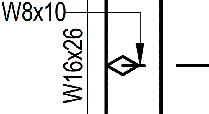
- "HIGH/LOW" steel: When beams at different elevations cross the same bay, drawings mark them "HIGH" and "LOW". Make sure you're capturing both members.
- Incomplete designations: Sometimes drawings show just the depth (W12) without the weight (W12x26 vs W12x40). Find the beam schedule or general notes that specify which W12 applies.
- Named frames and trusses: For callouts like "Frame Type A" or "Truss T-1", check detail sheets to find the actual members.
- Leaderlines: Callouts with long leader lines can point to distant members... trace carefully!
- Galvanization: Notes like "GALV" or "HDG" indicate hot-dip galvanized steel, which affects pricing and lead time. Easy to miss in general notes or schedules.
- Camber: Many beams have specified camber (curvature) noted in the schedule or callout. Each beam can have a different camber!
- Small and hidden beams: Some steel doesn't show up on the main framing plans, such as hoist beams. Other times, small steel beams surround a shaft or opening.
2. Columns
Columns can be trickier than beams. Unlike beams that run horizontally across the page, columns stick "out" of the page vertically - you're looking down at them from above. So where do we find the info, and how do we count them?
How did we figure that out though?
Question 1: Where are the columns?
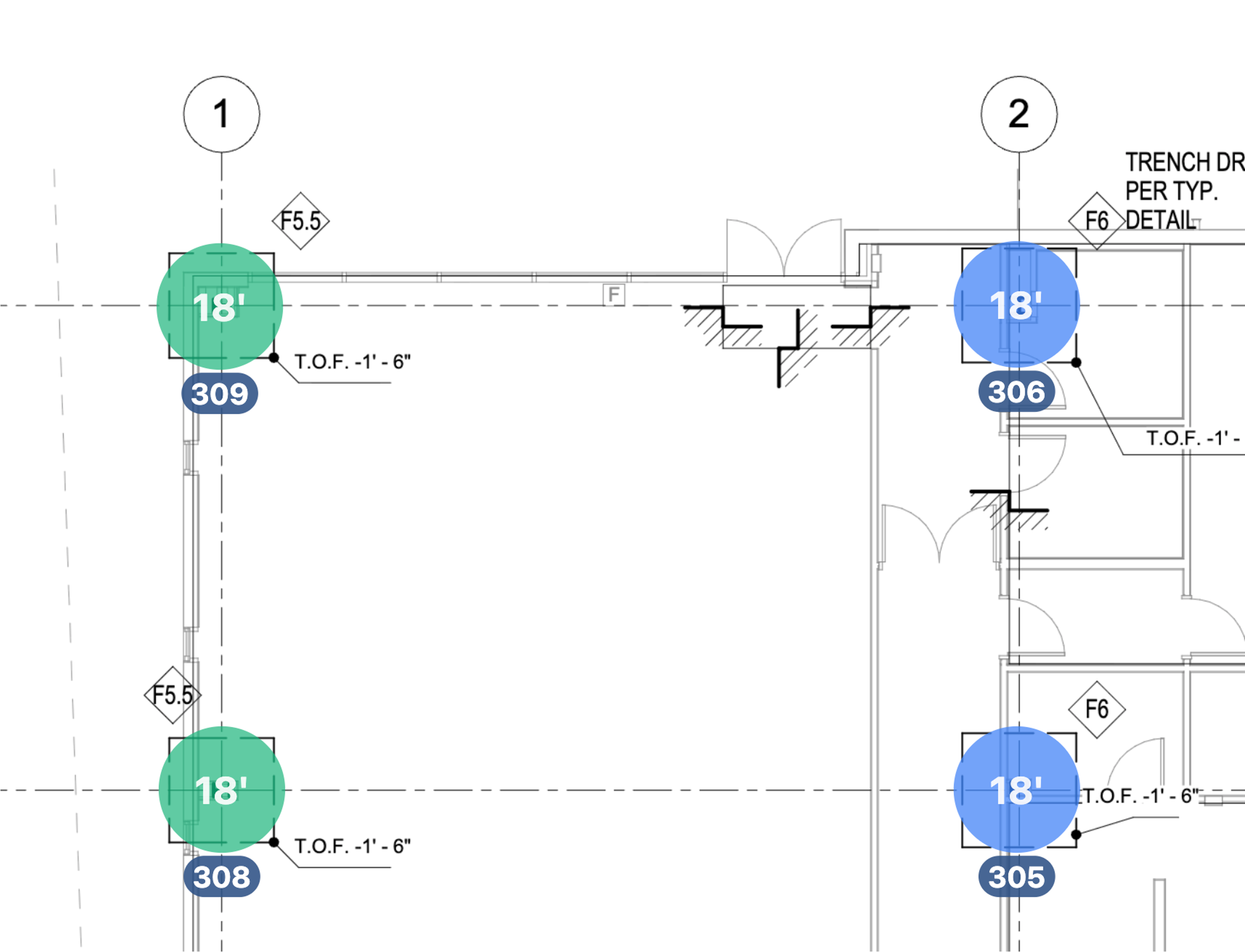
Almost always, the foundation plan shows column locations. This is your starting point — every column sits on a foundation or base plate.
However, in tall buildings or buildings with column splices, some columns may start on upper-level framing plans. Check each floor plan to catch columns that begin mid-building.
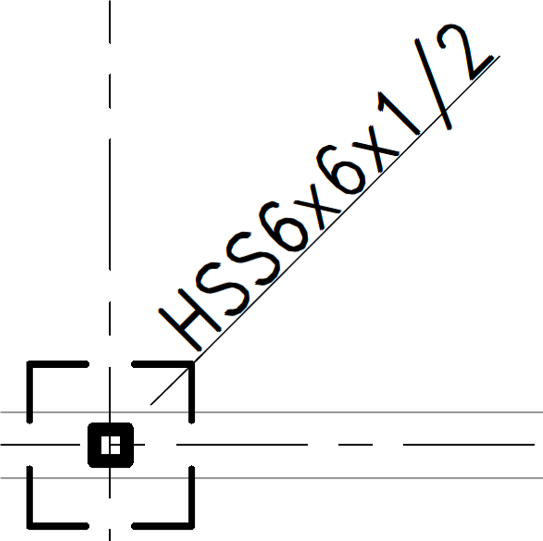
Typical hints of a column are a HSS or W-shaped profile, a concrete footing/pad, or a leader specifying the steel shape or C1, SC1, etc.
Question 2: Column Types
Next, for each column, what type of W, HSS, or other shape is it? (And let's hope it's not a cruciform column)
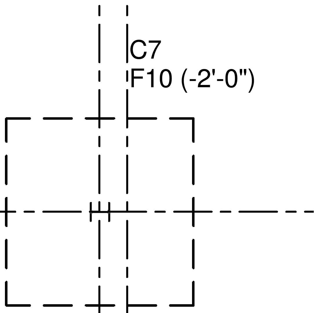
Look for callouts directly on the foundation plan, or cross-reference the column schedule that maps column marks (C1, C2, C3) to actual sizes (W14x90, HSS10x10x5/8, pipe 8" STD).
Question 3: Column Heights
Hint: It's rare to directly see these quantities for each column.
- Simplest Case: Column heights are directly labeled on the foundation or framing plan. This is rare - often general roof elevations are labeled as Top of Steel (TOS) or Bottom of Deck (BOD) at certain points, but you may have to interpolate to get each column height.
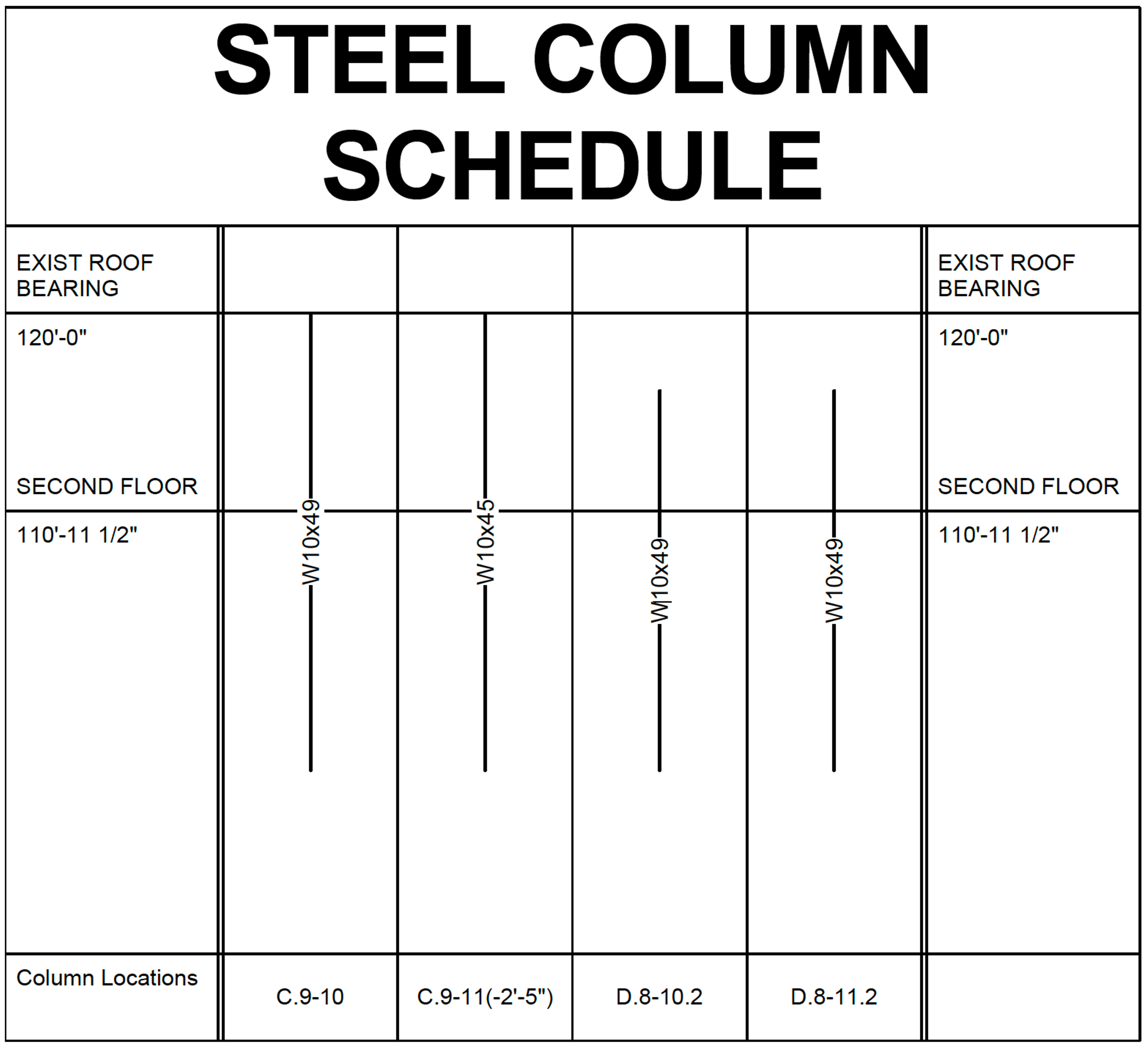
-
Medium Case: A column schedule shows heights of each column at each grid location.
-
Hard Case 1: Architectural diagrams where you have to mentally map grid locations to find elevations.
-
Hard Case 2: Cross-referencing multiple framing plans to piece together floor-to-floor heights.
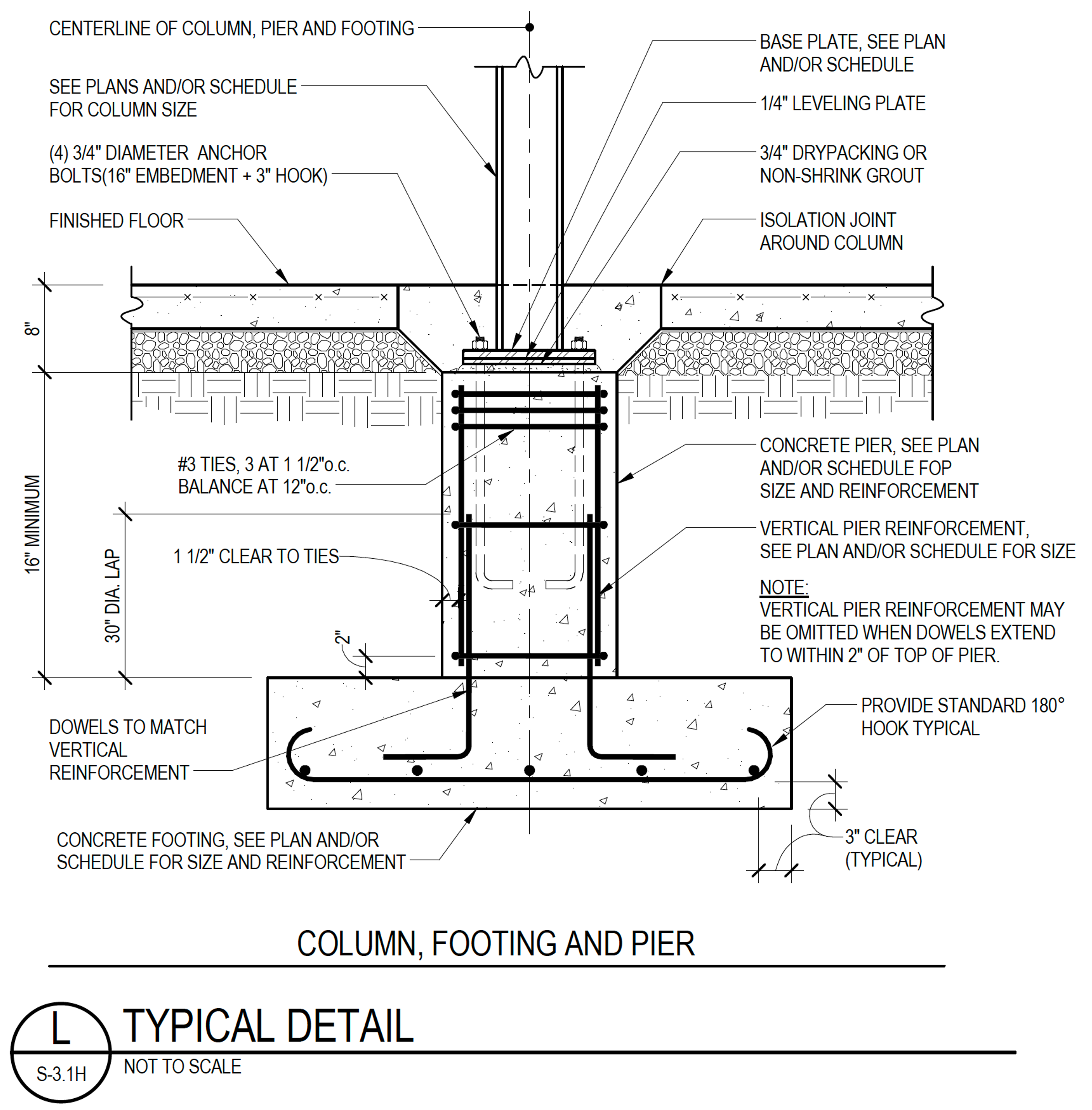
3. Base Plates
Base plates connect columns to foundations. They can weigh more than an average human and curl. Non-negligable mass, and a bunch of processing. Don't forget the holes and the bolts!
Location
This isn't too hard - base plates mostly occur where the column interfaces with the foundation.
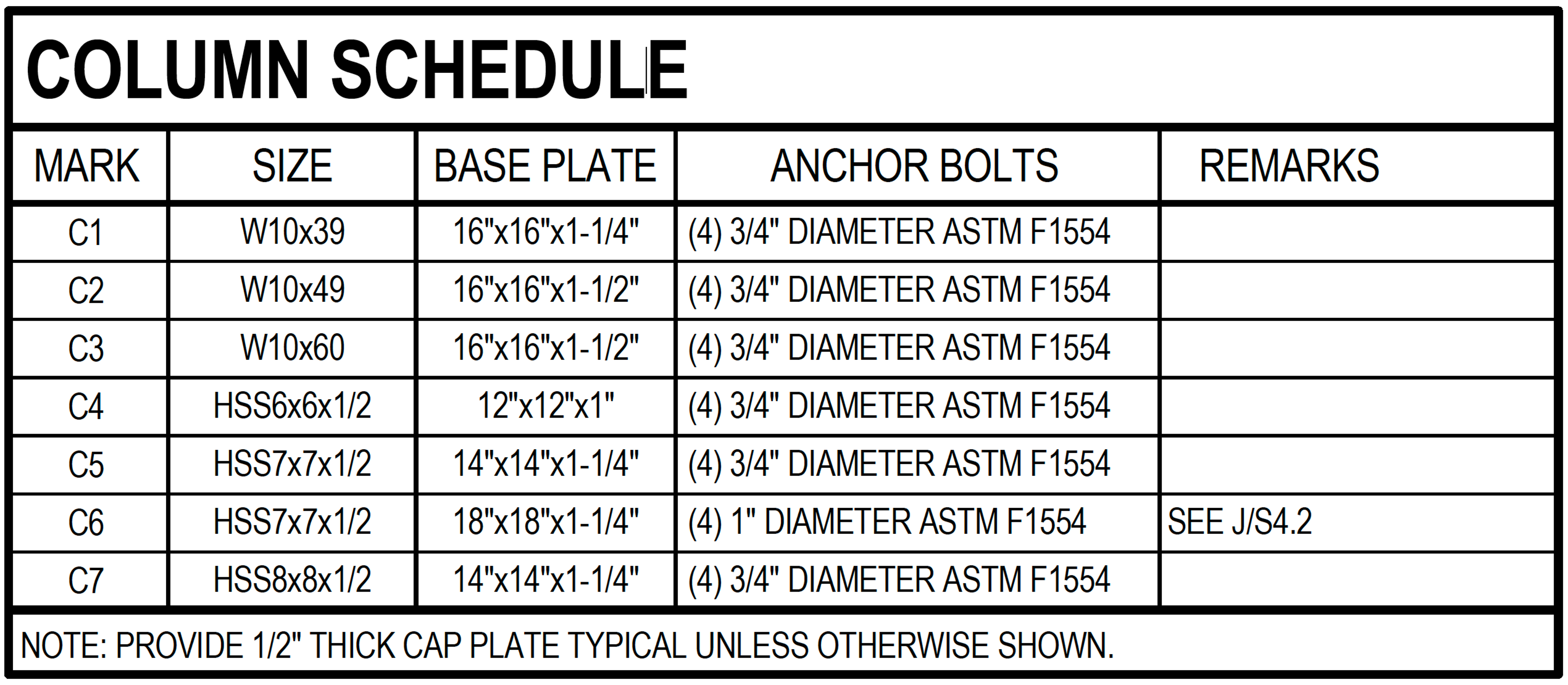
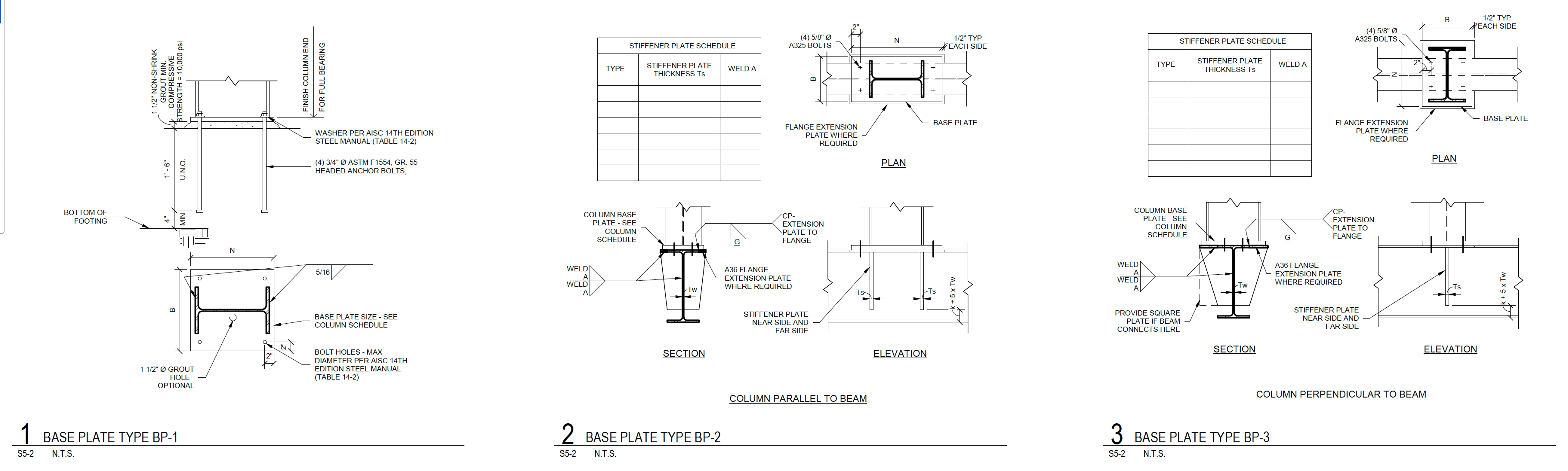
Base Plate Details
This is a bit harder - we need to specify all the details for each base plate:
- Plate dimensions: Width × Length × Thickness (e.g., 16" × 16" × 1")
- Material grade: Usually A36 or A572 Gr. 50
- Anchor bolts: Quantity, diameter, length, and grade (F1554 Gr. 36 is common)
- Hole pattern: For calculating plate weight and drilling
4. Connection Details: The Hardest Part
We've talked to 100s of fabricators, and in our own experience, we all agree. Getting the connection details right is the hardest part of estimating. Missing an angle iron along a connection can cost you $10k. While potentially small by weight (although can be 5-10%), there can be significant manufacturing effort to create, shape, and craft these pieces.
How We Think About Details
- Is this detail relevant? Does it fall within your scope of work? (Often GCs copy entire detail sheets, and many may not be even relevant.)
- What materials are present? What size and how many angle irons, bent plates, and purlins are involved in this connection.
- How many or how long is this detail applied? Count instances or measure linear footage across the structure.
- Bracing: HSS tubes, angles, or rods between columns—check lateral framing plans
- Kickers and struts: Small members that brace beams to slabs or walls
- Stiffeners: Plates welded inside beam webs at concentrated load points
- Bearing plates: Under heavy equipment or at beam seats on masonry
Final Thoughts
Material takeoff is where attention to detail matters. You miss a few pieces, and your bid can go from being profitable, to underwater.
At Alkali, we're building software to make steel takeoff faster and more accurate — with automated beam scanning, real-time collaboration, and AI-powered search. Try it free: